Finite element analysis of implants, plates and guides
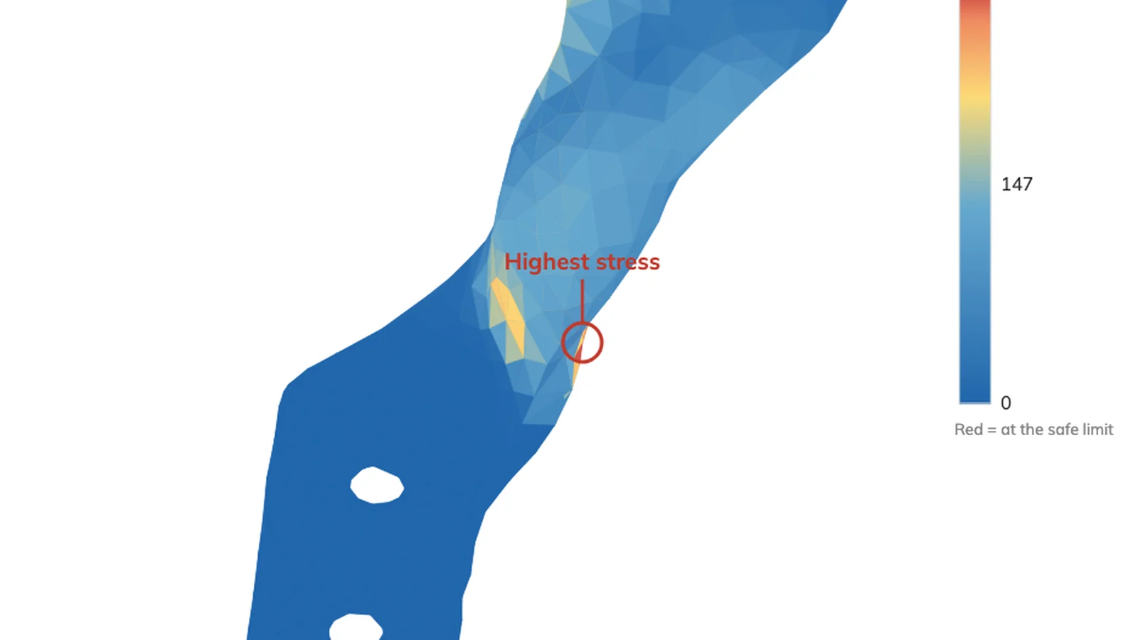
Implants, plates, fixation constructs and guides are analysed under a stated load case. The result is a safety factor against a stated criterion, with the peak located on the model and the limits of the analysis written down.
Most published work in this field cannot be reproduced from its own method section. Element type, mesh study and boundary conditions are stated in every report here, in the vocabulary of ASME V&V 40.
What is delivered
- Peak stress, its location on the model, and the safety factor against your stated criterion
- Verification evidence: element type validated against a closed-form solution, and the spread across repeat runs
- A written statement of what the analysis does not cover
- A full engineering report, and a short summary for clinical readers
Method and reporting
- Quadratic tetrahedral elements. Linear tetrahedra shear-lock in bending and under-report stress in thin walls, which overstates the safety factor
- Repeat runs at each mesh density, with the worst run reported and the spread stated, because meshing is not perfectly repeatable
- Load case, boundary conditions and acceptance criterion agreed with you in writing and fixed before the analysis runs, with the basis of each stated
What you provide
- The geometry, as STL or the native CAD file
- Material and its source, ideally a certificate naming the standard it was made to
- The load case, or a request that one be researched and cited for your device family
- The factor of safety the design is held to
How this is kept honest
Refusals Reported
A sharp internal corner has no converged stress. Where a number would be meaningless, the report says so instead of giving one.
Repeat Runs
Meshing is not perfectly repeatable. Repeat runs at each density establish the scatter, which is reported with the result.
Fixed Before It Runs
The load case, boundary conditions and acceptance criterion are settled with you before the analysis starts, so the criterion is never chosen to suit the answer.
Analysis, Not Design
The geometry is yours. Osteo3d does not design devices, and geometry sent for analysis is not altered or redistributed.
Frequently Asked
- Can this support a regulatory submission?
- The reports are written in the ASME V&V 40 credibility vocabulary and state their verification evidence and limits. Whether that evidence is sufficient for a given submission depends on the context of use and the model risk, which is assessed with you before work starts.
- What if there is no published load case for my device?
- The load case is researched, agreed with you and recorded with its basis stated. Where the literature does not support one, that is reported rather than a plausible number being chosen.
- Is a linear static analysis always appropriate?
- No. It assumes small displacements, and a result that violates that assumption is reported as out of range rather than presented as a stress. Fatigue and non-linear contact are separate analyses and are scoped separately.